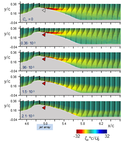
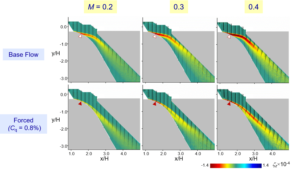
Flow separation is a commonly occurring engineering problem that occurs in both internal and external aerodynamics, and leads to negative effects such as increased drag, loss of lift, internal flow losses, and even increased aeroacoustic noise to name a few. As such, the elimination of flow separation has been a major research topic for decades. The premise has been based on controlling the flow either passively or actively to alter the boundary layer and near wall flow characteristics to delay and possibly eliminate the presence of separation. Passive flow control elements are such that they need no further input and are generally geometric alterations, such as vortex generators on airplane wings. Active control is more involved and requires external input either in the form of power for synthetic jets, or pressurized air in the case of the fluidic oscillators studied here. The global performance benefits of such passive and active control strategies are well documented in the literature. This project, however, is less focused on the performance of such devices, but rather on how the jets interact locally with the separated crossflow. Figures 1 and 2 show the effect of increasing the level of actuation through an array of surface embedded fluidic oscillators in a canonical separation case (Figure 1) and separation at the entrance to a branched diffuser duct (Figure 2).
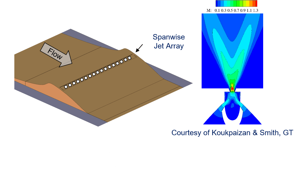
The model with a spanwise array of jets is shown in Figure 3, with a time averaged flow field of a single fluidic oscillating jet. The jet displays a dual velocity peak due to the oscillation, which allows a single jet to effect a much wider area than that of a non-oscillating jet. The model in Figure 3 allows us to not only examine the flow using particle image velocimetry (PIV) along the center plane (as was depicted in Figure 1), but also in the spanwise orientation using stereo-PIV with two cameras. This experimental setup allows for the examination of spanwise flow structure and interaction of the jets with the separated crossflow. Figure 4 depicts how the issuance of the fluidic oscillating jets quickly organizes the flow into a spanwise, periodic array of counter rotating concentrations of vorticity that are the underlying cause of the delayed flow separation. What is interesting to note is these concentrations persist in the instantaneous sense, as well as the time-averaged conditions. By understanding and delving deeper into the actual process and flow structure of the flow separation and re-attachment, flow control technology can be better understood, advanced, and integrated into future advanced aerodynamic designs.
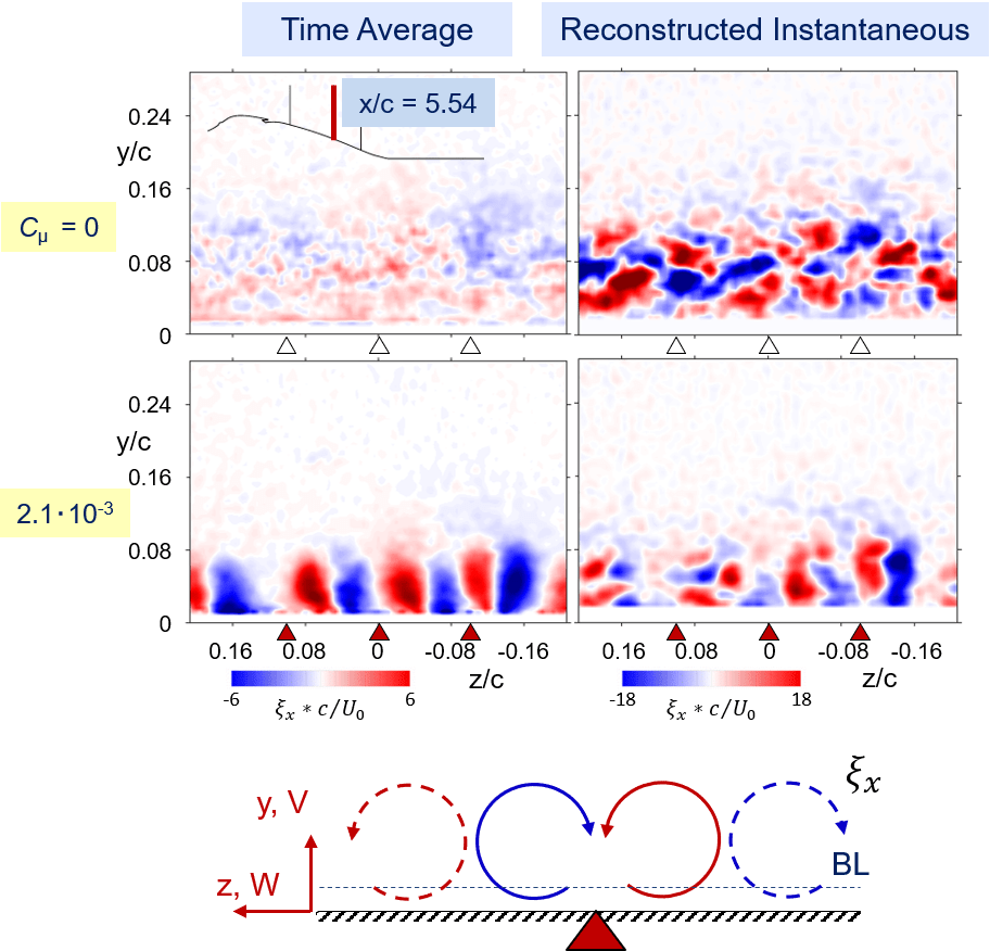
Figure 4. Spanwise PIV plane showing the incoherent, unactuated flow (top row) and the ensuing development of a coherent array of counter rotating vorticity concentrations formed over the surface due to the oscillating jets (bottom row).The sense of rotation is highlighted in the schematics at the bottom. Furthermore, the comparison is shown between a time averaged data set (left column) and instantaneous example (right column) of the two flow conditions, showing that even though the flow is highly unsteady the jets still force an organization of the flow similar to what is seen in the time averaged image.
Supported by GT-VLRCOE